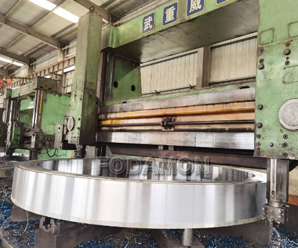
The cement industry rotary kiln is the core and key equipment of the cement plant, and the thermal properties of the riding ring and the supporting wheel are poor. At the same time, they are operated under high temperature and heavy load for a long time. In addition, the working environment is relatively harsh. Generally, pitting corrosion and peeling or severe fatigue damage occur. If not repaired in time, it will have a very serious impact on the normal production of the cement plant and huge economic losses. A company summarized the technology of wheel tyre repair in the maintenance of rotary kilns, which plays an important role in cement production lines.
- Overview
The inner diameter of the rotary kiln of the 3200t/d clinker cement production line of the cement company is Φ4.55m, the Ⅱ gear wheel belt weighs 41.9t, the total weight of the barrel of the Ⅱ gear wheel belt towards the kiln tail is 546t, and the barrel of the barrel towards the kiln head weighs 270t. Now the Ⅱ gear wheel belt needs to be removed and the wheel belt pad and wheel belt need to be replaced. Therefore, a 1m long barrel short section is cut off at 2m from the wheel belt towards the kiln head, and the wheel belt is lifted out with a car crane, and then a new wheel belt is replaced, and finally the barrel is restored. - Construction procedure
Preparation before construction → Making of support frame → Measuring the barrel and inspecting the new wheel belt → Installing the M-shaped frame → Cutting off the barrel short section and repairing the bevel → Lifting out the old wheel belt → Replace the wheel belt pad → Lifting the new wheel belt → Lifting the barrel short section → Adjusting the concentricity and length of the barrel → Welding the barrel → Adjusting the wheel belt → Welding the wheel belt block. - Construction Technology
3.1 Construction Preparation
Be familiar with the construction site, select the support point, measure the height from the bottom of the cylinder at the support point to the supporting ground, inspect the new wheel band, check the top clearance of the large gear, prepare a construction plan, collect construction materials, prepare construction machinery, etc. In short, the preparatory work before construction is very important. All possible situations should be considered as much as possible, and work closely with the construction management personnel of Party A to promptly eliminate various unfavorable factors that affect the work.
3.2 Production of Support Frame
The work mainly includes the production and installation of the support frame of the kiln head cylinder and the kiln tail cylinder. Two scaffolding frames need to be set up, namely one at the wheel hanging and one at the cutting cylinder. Select the support point and measure the elevation from the support point to the supporting ground. Use 325mm×8 steel pipes to make the legs, use 12mm steel plates to make steel beams, and make two arc-shaped brackets with the same outer diameter as the cylinder, 400mm wide.
3.3 Cut off the short section of the cylinder and repair the bevel
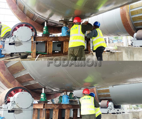
Use the prepared bracket to support the kiln cylinder at the selected support point. It is necessary to remake support I (made of steel pipe and steel section) and support II. The force of support I is calculated to be 1/2G1=1/2×546=273t, and the force of support II is 1/2G2=1/2×270=135t.
Draw a line 2m away from the second gear pulley in the direction of the kiln head, and cut off the cylinder with a length of 1m. Requirements: Draw a cutting circle on the cylinder, and then mark both sides of the cutting line in 8 equal parts. Measure the straightness of the cylinder and the distance between the kiln head and the kiln tail at the marked points and make a record. When the cylinder is restored, dock it at the point and measure the concentricity of the kiln head and the kiln tail. Add 1 “M”-shaped support on both sides of the cutting line inside the cutting cylinder (250mm from the cutting line), a total of 4, to prevent the cylinder from deforming; when cutting, the same cutting line is cut by 2 cutters at the same time; the cutting line of the cutting cylinder cannot overlap with the weld, and the spacing is more than 500mm; use a 25t truck crane to hang down the cut cylinder and trim the groove of the cylinder joint.
3.4 Lift out the old tire
After cutting off the cylinder, lift the cylinder with two 200t hydraulic jacks at support I, with the tire 50mm away from the support wheel; then remove the pad at the top of the tire first, and use this as the lifting point; use a 17mm steel wire rope to pass through the tire, with a total of 12 strands; finally, use a 130t truck crane to lift the tire. When the lifting height is 8mm, swing the crane mast to slowly drag the tire to separate the tire from the pad position; when the tire is dragged to the cut-off cylinder gap position, lift the tire to the ground.
3.5 Replace the tire pad
Cut off the screws of the old pad, remove the screws, and remove the old pads in sequence; install the new pads in sequence.
3.6 Lift the new tire
Use a 17mm steel wire rope to pass through the tire, with a total of 12 strands. Then use 130t and 25t truck cranes to stand up the wheel band and lean it against the kiln foundation. After threading the wire rope, use the 130t truck crane to lift it to the gap position, slowly put it into the cylinder, swing the crane mast to make the midpoint of the wheel band coincide with the midpoint of the pad. After it is in place and temporarily fixed, lower the previous support frame I to make the wheel band contact the support wheel.
3.7 Hoisting the cylinder short section
First, prepare the lap plate, connection block, connection bolt, adjustment pressure plate, top screw and other kiln interface tools before hoisting the cylinder. Use a 25t truck crane to install the cylinder short section with the groove. During the docking process, keep the cylinder misalignment ≤2mm. Measure the overall length of the cylinder, within the deviation range, and then spot weld.
3.8 Adjust the concentricity and length of the cylinder
Set up a fixed bracket at the kiln head, kiln tail, large gear ring and two welds, use the auxiliary motor to rotate the rotary kiln, measure the distance from the fixed bracket to the cylinder surface, take 8 equal parts to calculate the cylinder core, and use the original measurement data as the standard; use the pull code and top screw to adjust the cylinder core of the kiln cylinder; the allowable deviation of the cylinder core of the kiln cylinder is as follows: 5mm for the kiln head and kiln tail, 12mm for other positions, and 4mm for the large gear ring.
3.9 Welding the cylinder
Bevel the cylinder. Use a single-sided “V” bevel with a blunt edge, with a gap of 3mm, and a 3mm steel sheet in the middle (placed in 24 equal parts) to prevent welding shrinkage and cause the length of the cylinder to become longer.
Use CO2 gas shielded welding method for base, filling and capping, use multi-pass welding, and carbon arc gouging for back root cleaning. The welding procedure and arc starting point of each weld should be arranged according to the measurement results of the center line of the kiln shell. When welding, the maximum bending point should be turned to the highest point, and the center line bending of the kiln shell should be corrected by the weight of the kiln shell itself.
In order to reduce welding deformation, two people can operate one weld symmetrically at the same time. The welding work should first weld the weld near the large gear ring to reduce the influence of welding deformation on the large gear ring. And pay attention to the following points.
(1) To ensure the quality of welding, a small hammer should be used to knock the weld after each layer is welded to release the welding stress, and a wire brush should be used to remove welding slag, weld nodules, etc., and then a grinding wheel should be used to clean the gaps on both sides of the groove to ensure smoothness without slag inclusions. Finally, a steel brush should be used to remove debris in the weld.
(2) After each layer is welded, the center line of the kiln shell is detected once, and the starting point of the next welding is determined based on the measurement results, but the arc starting position of each layer should be staggered by more than 50mm.
(3) Tightening bolts, adjustment blocks and other parts at the weld can only be cut off after the weld reaches sufficient strength. Arc gas cutting is not allowed to be used to cut off the above objects to avoid damaging the cylinder. Flame cutting can be used.
Welding quality requirements after welding: The weld excess height in the cylinder is 0-1.5mm, and there shall be no undercut, slag inclusion, pores, cracks and other phenomena on the weld surface; ultrasonic flaw detection is used, and the flaw detection length is not less than 25% of the weld. The quality assessment reaches Grade II in GB11345 to be qualified.
3.10 Adjusting the wheel band
The wheel band is divided into 8 equal parts, and the rotary kiln is rotated by the rotary kiln’s turning device. The wheel band is adjusted with 2 dial indicators; the radial runout is required to be 1mm and the end face runout is required to be 2mm.
3.11 Welding the wheel band stopper
After the wheel band is adjusted, the wheel band stopper is welded symmetrically with CO2 gas shielded welding, and the weld angle height is required to be 15mm.
The experience gained through practice is fully reflected in the maintenance of important equipment such as kiln tires. Therefore, Fodamon engineers said that in the maintenance of kiln tires, replacement, alignment and correction are the key technologies to solve the problem.